
What is an Oscilloscope?

|
|
|
 |
3/4GHz, 12-Bit, 20GSa/s, 1Gpts HKD 150,000 up |
 |
300/500/1000MHz, 12-Bit, 4GS/s, 400Mpts HKD 28,000 up |
 |
100/200MHz, 12-Bit, 2GS/s, 100Mpts HKD 7,000 up |
 |
1/ 2.5/ 4/ 6/ 8/ 10 GHz, 50GS/s, 12-Bit, 1Gpts HKD 338,000 up |
 |
350/ 500/ 1000/ 2000 MHz, 6.25GS/s, 12-Bit, 500Mpts HKD 178,000 up |
What Does an Oscilloscope Measure?
Oscilloscope measurements primarily involve capturing voltage waves over time, with voltage displayed vertically on the Y-axis and time on the X-axis. Waveform intensity may also be shown on the Z-axis. This device enables the analysis of various electrical properties based on the displayed waveforms, allowing users to assess aspects as follows:- Current: Measured using a current probe or by assessing voltage drop across a resistor.
- Sound: Analyzed by converting audio signals into voltage with a transducer.
- Capacitance: Indirectly gauged by calculating time constants in circuits.
- DC Voltage: Determined manually by counting vertical divisions and multiplying by the volts per division.
- Inductance: Estimated using a function generator but typically with an uncertainty rate of 3-5%.
- Frequency: Measured either automatically or manually by calculating the period of the waveform and inverting it.
How to Read the Signal Characteristics with Oscilloscopes
Oscilloscopes are used to check several important aspects of signals to ensure they are working correctly. Here are the most essential parts engineers focus on:
Signal Integrity and Timing
Engineers first look at the signal shape, making sure it matches the expected pattern, whether it’s a sine, square, or sawtooth wave. Any changes in shape could indicate a problem.
They also check the amplitude, which is the strength or voltage of the signal, to make sure it stays within the right range. If the signal fluctuates too much, it can be a sign of issues with the power supply or the circuit.
The frequency or period is another key aspect, ensuring the signal repeats at the right speed. If the frequency is off, it can cause problems in communication or control systems. For digital signals, the rise and fall times need to be sharp and clear. Slow rises or falls can cause data errors, while fast ones might cause interference and other signal problems.
Noise, Distortion, and Synchronization
Jitter is another issue engineers check for. It refers to small timing changes in the signal, which can cause errors in high-speed systems.
Different types of jitter, like period jitter or cycle-to-cycle jitter, can affect the signal's consistency, leading to communication errors. Engineers also look for noise, which is any unwanted interference in the signal. Too much noise can distort the signal, making it unreliable.
They check harmonics and distortion, especially in analog signals, to ensure the signal stays clear and accurate. Ringing and crosstalk are also monitored. Ringing occurs when the signal keeps oscillating after a change, while crosstalk happens when signals from other lines interfere with the one being measured. Both can mess up the signal and cause errors.
Stability and Anomalies
Engineers also check for ground bounce, which happens when the ground potential fluctuates, especially in fast digital circuits. This can create noise in the signal. If the signal goes beyond the oscilloscope’s input limits, it will be clipped, meaning the waveform will be cut off.
This indicates the signal is too strong and needs to be adjusted. DC offsets are another concern. If there’s an unexpected shift in the baseline of the signal, it could point to issues with the way the signal is generated or connected.
Lastly, engineers watch for aliasing, which happens when the oscilloscope samples the signal too slowly, creating an incorrect version of the waveform. This can cause major problems with signal analysis and needs to be avoided.How Does an Oscilloscope Work?
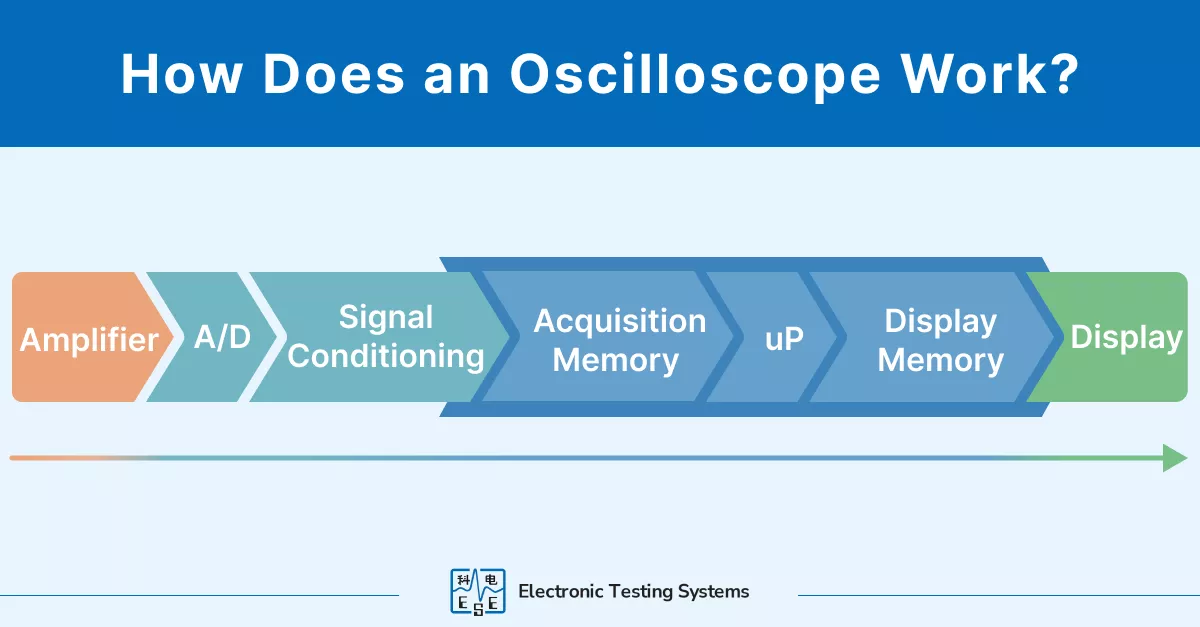
From signal acquisition to display, here are the operational stages of an oscilloscope and how it processes and visualizes electrical signals.
- Signal Acquisition: The oscilloscope captures electrical signals via input connectors connected to probes, which can receive signals from various electronic sources.
- Signal Amplification: To enhance visibility and precision, the oscilloscope amplifies the incoming signal to a level suitable for detailed display analysis. It then uses an analog-to-digital converter (ADC) to sample the signal voltage and convert it into a digital format for further processing.
- Horizontal Deflection: The time-based control generates a horizontal sweep, mapping time across the display to track how signals evolve. The sample clock within the horizontal system assigns accurate time coordinates to each voltage sample, driving the ADC. This process ensures the digital output is reliably stored in the acquisition memory for detailed analysis.
Oscilloscopes offer several sweep modes to handle a range of applications:
- Auto Sweep: Automatically starts a sweep even without a stable trigger, ensuring the display remains active. This mode is ideal for analyzing erratic or unpredictable signals but sacrifices some precision.
- Normal Sweep: Only begins a sweep when a signal meets the trigger condition, providing highly accurate waveforms. It’s best suited for stable, repetitive signals like clock pulses or sine waves.
- Single Sweep: Captures a single event, such as a transient spike, and stops after the sweep. This mode is perfect for isolating and studying one-time events but requires careful setup to avoid missing the signal.
- Vertical Deflection: The signal's voltage is mapped to the vertical scale of the display, allowing the user to adjust the vertical position and sensitivity to better visualize signal amplitude.
- Triggering: The trigger system stabilizes the waveform display by refreshing the screen at a specific point in the signal, as set by the user. This step ensures the consistent visualization of the waveform, using the predetermined condition as a time reference to anchor the display.
- Display: The oscilloscope displays the event that meets the trigger criteria with the visualized signals on the screen, including the waveform data before and after the event, allowing for a detailed examination of the signal behaviors.
Basic Systems of an Oscilloscope
An oscilloscope's functionality is categorized into three main groups based on its internal components and their roles:- Display and Interface: Modern oscilloscopes use LCD or LED panels for clear waveform visualization. The interface includes the vertical system with controls for signal amplitude, such as the volts-per-division selector and vertical beam position, and the horizontal system that manages the time base with selectors for seconds-per-division and beam positioning.
- Signal Processing: This includes the amplifier/attenuator which adjusts signal amplitude to prevent damage and ensure accuracy. The ADC (Analog-to-Digital Converter) then processes these signals by converting them into digital data, which is stored in memory for later analysis.
- Control and Measurement: The oscilloscope's probe acts as the point of connection to the circuit under test, suitable for different types of measurements. The trigger system stabilizes the waveform by initiating data capture under specific conditions. Control logic in digital oscilloscopes allows for flexible and precise configuration of capture settings, while the time base regulates the display's horizontal axis to effectively capture varying signal speeds.
How to Choose the Right Oscilloscope
Choosing the right oscilloscope involves understanding key factors that affect performance and accuracy, ensuring optimal functionality for specific applications. Here's what to consider:
Vertical Sensitivity
This refers to the ability of an oscilloscope to describe how effectively the vertical amplifier can accurately amplify weak signals, with its capacity typically measured in millivolts per division. High vertical sensitivity is crucial for detecting small changes in signal amplitude, which can be important in applications such as small-signal circuit testing or monitoring low-voltage sensors.Bandwidth
The bandwidth determines how well the oscilloscope can measure high-frequency signals. A rule of thumb is to select a bandwidth that is at least three to five times higher than the highest frequency to be measured to avoid aliasing and signal distortion. This ensures that the waveform's characteristics are accurately captured, which is crucial for applications such as high-speed digital signal testing where precision matters.Sample Rate
The sample rate affects the oscilloscope's ability to accurately reconstruct a waveform. A higher sample rate provides a more accurate depiction of the waveform, which is essential for capturing transient details and minimizing sampling errors. Generally, a sample rate that is at least four to five times the real-time bandwidth is recommended to ensure that the waveform is well-defined and anomalies are not missed.Number of Channels
More channels allow simultaneous observation and comparison of multiple signals or waveforms, which is beneficial in complex systems analysis. This can dramatically reduce troubleshooting time and enhance the capability to diagnose system interactions and problems, especially in multi-channel systems like phased array systems.Display Quality
A high-resolution display is vital for distinguishing between fine details in waveforms. Good display quality can help in identifying subtle waveform anomalies, which might indicate problems in the circuit's function. This is particularly important when fine-tuning a system's performance or when dealing with complex signal structures.Memory Depth
The memory depth determines how long an oscilloscope can capture data at its full sampling rate. A deeper memory allows for longer time captures at a high resolution, essential for analyzing complex and long-duration signals. This can impact the effectiveness of debugging, especially in systems where issues occur sporadically or over long periods.Waveform Capture Rate
The waveform capture rate indicates how many waveforms an oscilloscope can acquire and display per second, measured in waveforms per second (wfms/s). A higher capture rate increases the likelihood of detecting rare or intermittent signal anomalies, as the oscilloscope spends less time processing and more time capturing data. This is crucial for accurately observing and troubleshooting high-speed or irregular signals.
Rise Time
It defines the oscilloscope’s ability to accurately capture fast transitions within a signal. A shorter rise time allows the oscilloscope to handle higher frequencies and more rapidly changing signals, making it essential for high-speed electronics where precision in capturing edge transitions is required for effective analysis and troubleshooting.Triggering Capabilities
Triggering capabilities enable the isolation of distinct signal events, maintain stability in repetitive waveforms, and deliver precise signal characterization. A more advanced triggering system allows for a more precise capture of event-related data. This is particularly important in digital circuits or serial applications where specific conditions or errors need to be captured for proper analysis. Common trigger types include:- Edge Trigger: Activates the sweep when the signal crosses a specified voltage threshold in a particular direction (rising or falling).
- Pulse Width Trigger: Initiates the sweep when a pulse exceeds or falls short of a set duration, useful for detecting anomalies like glitches.
- Video Trigger: Designed for video signals, it triggers on specific lines or fields, aiding in the analysis of video-related waveforms.
Advanced triggering options enhance the oscilloscope's ability to capture complex signal behaviors, making them essential for detailed analysis.
Probes
Probes connect the oscilloscope to the test circuit, transmitting signals for measurement. Choosing a probe that matches the signal characteristics and frequency range of your application is crucial as it ensures precise measurements. Common types include:
- Passive Probes: The most common type, ideal for low-frequency measurements. They contain only passive components like resistors and capacitors and do not require external power.
- Active Probes: Designed for high-frequency signals, these probes include active components like amplifiers and transistors, improving signal fidelity. They require external power to operate.
- Differential Probes: Equipped with two sensing leads, these probes measure the voltage difference between two points without grounding either lead, making them essential for differential signals.
- Current Probes: Specialized for current measurements. They come in clamp-on versions that avoid circuit interruption and in-line versions connected directly in series with the circuit.
Effective Number of Bits (ENOB)
ENOB quantifies an oscilloscope's actual resolution, accounting for noise and distortion. It reflects the number of bits of a perfect digitizer required to achieve the same signal-to-noise ratio as the oscilloscope in question. A higher ENOB indicates better accuracy and fidelity in signal representation, which is particularly important when analyzing small signal details or when precise measurements are critical.
Software
The oscilloscope's software significantly impacts usability and functionality. Advanced software enables automated measurements, waveform analysis, and data sharing. It also provides features like customizable interfaces, remote operation, and integration with other tools. Choosing the right software ensures efficient workflow, simplifies complex tasks, and enhances productivity, making it a crucial factor for both basic and advanced applications.
Differernt Types of Oscilloscope
There are two types of oscilloscopes: analog and digital. Analog oscilloscopes were preferred for their real-time waveform display, but limitations in storing and triggering waveforms led to the rise of digital storage oscilloscopes. These digital versions offer advanced features like multiple triggers and PC connectivity but struggle with displaying real-time waveforms. Let’s take a closer look at these 2 types of oscilloscopes.Analog
Analog oscilloscopes use a cathode ray tube (CRT) to display waveforms, where an amplified input signal deflects an electron beam across the screen to visualize changes in real time. These scopes are excellent for showing continuous, rapidly changing waveforms. However, due to their limitations in stable triggering and waveform storage, along with a lack of advanced features and measurement capabilities, the use of digital storage oscilloscopes has become more prevalent in handling complex data needs in modern electronics.Digital
Digital oscilloscopes transform analog signals into digital format using an analog-to-digital converter (ADC). This capability allows them to process and display data as waveforms on LCD or LED screens.With digital technology, these oscilloscopes facilitate complex analysis, including simultaneous display of multiple waveforms, storage of data for future review, and precise automatic measurements. They are equipped with advanced features such as waveform storage, detailed analysis tools, and mathematical functions, meeting diverse needs across various types.
Ranging from general-purpose models to more sophisticated and expensive variants, there are 5 common kinds of digital oscilloscopes:
- Digital Storage Oscilloscope (DSO): Ideal for capturing, recalling, and storing waveforms for later analysis, especially suited for high-speed, multichannel design applications with low repetition rates.
- Digital Phosphor Oscilloscope (DPO): Offers real-time Z-axis (intensity) visualization, enhancing the digital storage capability with advanced acquisition techniques for a clearer display of complex signals. Widely used for advanced applications like communication mask testing and intermittent signal debugging.
- Mixed Signal Oscilloscope (MSO): Combines the features of a digital oscilloscope with additional digital inputs, enabling simultaneous analysis of both analog and digital signals. It is particularly effective for debugging digital circuits.
- Mixed Domain Oscilloscope (MDO): Extends MSO capabilities by integrating a spectrum analyzer for RF(Radio Frequency) debugging along with standard analog and digital signal analysis.
- Digital Sampling Oscilloscope: Specializes in very high-speed signal analysis, providing jitter and noise analysis with exceptional accuracy. It achieves significantly higher bandwidth and timing resolution for analyzing repetitive signals than other types of oscilloscopes.
In general, while digital oscilloscopes are favored today for their advanced features and versatility, analog oscilloscopes still have their place in specific applications and educational settings.
Difference Between Oscilloscope and Other Testers
Testing and analyzing electrical signals requires the right tools, but not all testers serve the same purpose. Oscilloscopes, digital multimeters, voltmeters, and spectrum analyzers each have distinct strengths. Knowing their differences can help you choose the right device for your needs, whether you're measuring steady values or decoding complex waveforms.
Oscilloscope vs. Digital Multimeter vs. Voltmeter
A digital multimeter (DMM) measures voltage, current, and resistance, providing precise numerical readings. A voltmeter specifically measures voltage levels. Both tools give steady-state values but don't show how signals change over time. In contrast, an oscilloscope displays the waveform of a signal, revealing details like noise, glitches, or fluctuations that DMMs and voltmeters can't detect.
However, oscilloscopes may have larger input offset errors and lower resolution compared to multimeters, but they offer much higher sampling rates, making them essential for observing dynamic signal changes.
Oscilloscope vs. Spectrum Analyzer
Both oscilloscopes and spectrum analyzers are used to examine electrical signals, but they present data differently. An oscilloscope shows how a signal varies over time, with time on the horizontal axis. A spectrum analyzer displays signal amplitude versus frequency, with frequency on the horizontal axis.
This means oscilloscopes are ideal for observing time-domain characteristics like pulse shapes, while spectrum analyzers are better for analyzing the frequency components of signals, such as identifying harmonics or interference.
|
|
|
|
|
|
|
|
|
|
|
|
|
|
|
|
|
|
|
|
|
|
|
|
|
|
|
|
|
|
How to Use an Oscilloscope: Step by Step
Using an oscilloscope allows you to visualize and analyze electrical signals, which is essential for troubleshooting and designing electronic circuits. Here's a step-by-step guide to help you get started:
- Proper Grounding: Before connecting your oscilloscope to a circuit, ensure it's properly grounded. This step is crucial for both your safety and the protection of the circuit components. Connect the oscilloscope's ground terminal to the circuit's ground to prevent potential hazards.
- Connect the Probes: Attach the oscilloscope probes to the circuit of the device under test. The probe's tip connects to the point where you want to measure the signal, and the ground clip attaches to the circuit's ground. Ensure a secure connection to obtain accurate measurements.
- Power On the Oscilloscope: Turn on the oscilloscope using the power button. Upon startup, you might see a flat line on the display, indicating no signal is present. This is normal when no input is connected.
- Adjust Vertical and Horizontal Controls: Set the vertical scale (volts per division) to match the expected signal amplitude. Adjust the horizontal scale (time per division) to suit the signal's frequency. These adjustments help in properly displaying the waveform on the screen.
- Set the Trigger: Configure the trigger settings to stabilize the waveform. Adjust the trigger level and source to ensure a stable and clear display of the signal. This step is vital for capturing repetitive waveforms accurately.
- Calibrate the Instrument: Perform a calibration to ensure the oscilloscope provides accurate measurements. Follow the manufacturer's instructions for calibration procedures, which may involve adjusting internal settings or using a known reference signal.
Capture and Analyze the Signal: With the oscilloscope properly set up, observe the waveform on the display. Use the measurement tools to analyze signal characteristics such as amplitude, frequency, rise time, and any anomalies. Read into the signals and try to troubleshoot any potential problems.
Applications of Oscilloscopes
Electronics
Moreover, technicians can also use oscilloscopes to troubleshoot and repair electronics in devices like radios, TVs, computers, or other audio-video systems. They assess and test signal integrity and timing, crucial for maintaining the functionality of communication devices and networks.
Educational and Research
Vehicle Repair
Healthcare
Automotive
Oscilloscopes are indispensable in the automotive industry, providing critical insights into the performance of electrical systems. Mechanics use them to diagnose issues in starting systems, fuel injectors, and radar components by analyzing detailed electronic waveforms. They are also essential for testing in-vehicle network protocols like CAN, LIN, FlexRay, and automotive Ethernet, ensuring seamless communication between electronic control units and vehicle subsystems.
Aerospace
In aerospace, oscilloscopes are essential tools for ensuring the reliability and performance of complex systems. They validate radar functionality and check compliance with stringent communication standards such as MIL-STD 1553 and ARINC 429. By analyzing high-speed data links and detecting signal anomalies, oscilloscopes play a vital role in developing and maintaining critical avionics systems.
High-Speed Network
In the telecom and fiber optics sectors, oscilloscopes are key to advancing high-speed networks. They are used to test 5G and 6G systems, including mmWave signals and phased-array antennas, ensuring performance and compliance. In fiber optics, they verify optical transceivers and assess modulation formats like PAM4, ensuring data links meet IEEE and OIF standards. With the ability to measure frequencies up to 110 GHz, oscilloscopes are indispensable for driving innovation in communication technologies.
Contact Us
![]()
ESE Electrical Testing Systems
Leading distributor of electronic testing systems in Asia with 40+ years of professional experience.