Achieving Accurate Power Measurement for EV Development: Insights and Solutions
The global shift toward electric vehicles (EVs) is a critical step in reducing carbon emissions and promoting sustainable transportation. At the heart of this transition lies the need for accurate power measurement, which is essential for the development of efficient motor drive inverters—the core components that convert DC power to three-phase AC power for motor control. Accurate measurement ensures optimal inverter operation, enhancing the overall performance and efficiency of EV systems.
As the demand for high-performance EVs grows, power analyzers must handle the complexities of PWM (Pulse Width Modulation) control systems, in this blog we explore the challenges of measuring distorted waveforms, the role of bandwidth and phase correction, and how Yokogawa's WT5000 Precision Power Analyzer help solve above issues, outlined in Yokogawa's technical paper, Bandwidth and Phase Characteristic Requirements for High-Precision Power Measurement of High-Frequency and High-Current PWM Control Inverters.
Key Challenges in Measuring PWM Control Inverter Output
1. Distorted Waveforms and Active Power Over a Wide Bandwidth
PWM signals inherently produce distorted voltage and current waveforms due to the rapid switching of the inverter. These distortions introduce harmonics and non-linearities that complicate the measurement process. Traditional power measurement techniques, which assume sinusoidal waveforms, fall short in capturing the full spectrum of these signals. Accurate power measurement in such systems must account for both DC and harmonic components, as expressed by Equation (1):
P = U₀I₀ + Σ UₖIₖcos(ϕiₖ − ϕuₖ)
Here:
- U₀ and I₀ are the DC voltage and current components, respectively.
- Uₖ and Iₖ represent the RMS values of the harmonic components at the k-th frequency.
- ϕiₖ and ϕuₖ are the respective phase angles of current and voltage for each harmonic.
This equation highlights the importance of measuring across a wide bandwidth, as active power is derived from the sum of the DC and harmonic power components. If the bandwidth is insufficient, critical harmonic information is lost, resulting in inaccurate power calculations.
2. Bandwidth Requirements for PWM Inverters
The power output of a PWM inverter is composed of two main frequency bands:
- Fundamental Frequency Band: Corresponds to motor rotation (e.g., 100 Hz for an 8-pole motor running at 1500 RPM).
- Carrier Frequency Band: Contains higher frequencies dictated by the PWM carrier (e.g., 10 kHz or more).
To achieve accurate active power measurements, the measurement bandwidth must be several times greater than the highest frequency component present in the PWM signal.
Figure 3 illustrates how active power increases as the measurement bandwidth expands. This growth eventually saturates, demonstrating that the bandwidth must encompass the fundamental frequency and significant carrier frequency components.

3. Phase Errors and Current Sensor Propagation Delays
Phase discrepancies between voltage and current signals are a significant source of error in active power calculations, particularly in systems using current sensors with propagation delays. These delays introduce misalignment in the voltage-current phase relationship, directly affecting power factor calculations and overall accuracy.
However, in the high-frequency band, two key factors mitigate the impact of phase errors:
- Inductance Dominates: The inductive reactance (Xₗ = 2πfL) of motor loads increases with frequency, resulting in a near-zero power factor (cos φ ≈ 0). This means the active power contribution from high-frequency components is minimal.
- Apparent Power is Small: Due to the inductive nature of the load, the current at high frequencies is suppressed, reducing the overall apparent power.
Despite this, phase correction remains critical for accurate measurements, especially in the fundamental and lower-frequency bands, where most of the active power resides.
Figure 4 demonstrates how phase correction mitigates errors caused by propagation delays, ensuring accurate active power measurements across all frequency ranges.

4. Inductive Load Characteristics and Frequency Dependency
The behavior of inductive loads, such as motors, adds another layer of complexity to power measurement. The inductance (Lm) of the motor affects how current flows at different frequencies:
- At Low Frequencies: The inductive reactance is small, allowing current to flow more freely, leading to significant contributions to active power.
- At High Frequencies: The inductance suppresses current flow, resulting in reduced apparent power and minimal active power contribution.
This frequency-dependent behavior underscores the importance of advanced power analyzers capable of accurately capturing both the fundamental and harmonic components while compensating for phase errors introduced by inductive loads.
Key Factors and Best Practices for Accurate PWM Measurement
Sampling Rate and Bandwidth:
The power analyzer should have a high sampling rate and sufficient bandwidth. A general guideline is that the bandwidth should be three to five times the maximum fundamental frequency to accurately capture harmonics. For PWM applications, this typically means a bandwidth of at least 200 kHz to handle the switching frequencies effectively1.
True RMS Measurement:
The ability to perform true root-mean-square (RMS) measurements is critical, especially for non-sinusoidal waveforms common in PWM signals. This ensures accurate readings of voltage and current, regardless of waveform shape 1 2.
Phase Measurement Accuracy:
Accurate phase measurement is essential for calculating power factor and efficiency in PWM systems. The power analyzer should minimize phase errors due to propagation delays through advanced signal processing techniques 3 .
Current Sensor Quality:
High-quality current sensors integrated into the power analyzer can enhance measurement accuracy by providing precise current readings even under varying load conditions. This is particularly important for applications with rapid changes in load, such as those found in PWM systems4 .
Qualities of Effective Power Analyzers for PWM Testing
High Accuracy:
Look for devices with basic accuracy specifications within ±0.02% to ±0.05%.
Wide Frequency Range:
An operational range from DC up to at least 2 MHz is ideal for high-frequency applications.
Multiple Input Channels:
Support for multiple channels (at least four) allows simultaneous measurements across different phases.
The Yokogawa Advantage: WT5000 and CT Series
Yokogawa WT5000 Precision Power Analyzer
The WT5000 is a flagship power analyzer designed for high-precision applications in EV motor and inverter development. Its features include:
- Unmatched Accuracy: With a basic accuracy of ±0.02%, it is one of the most precise power analyzers available.
- Wide Bandwidth: Covers DC to 2 MHz, ensuring all relevant PWM frequencies and harmonics are captured.
- Phase Correction Capabilities: Corrects phase errors caused by current sensor delays, improving measurement accuracy.
- Versatile Functions: Supports active, reactive, and apparent power measurements, as well as harmonics analysis.
CT Series Current Sensors
The CT Series sensors, such as the CT1000A, complement the WT5000 by delivering accurate current measurements. Key features include:
- Minimal Propagation Delay: Reduces phase errors in high-frequency measurements (e.g., only 10 ns for CT1000A).
- Wide Frequency Range: Operates seamlessly with signals extending into the MHz range.
- High Accuracy: Ensures reliable performance, even in demanding PWM applications.
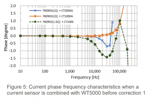
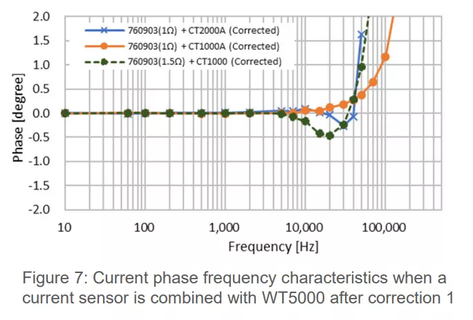
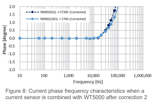
The WT5000 employs a method of setting the phase error value at a specific frequency as a function to correct the propagation delay time of a current sensor. Figures 5, 6, 7, and 8 show the phase characteristics when the corrections were made using CT sensors:
Figure 9 illustrates the measurement results when current sensors (CT1000A and CT200) are used to measure the power conversion efficiency of a three-phase PWM control inverter. The measurements with the CT1000A before and after phase correction are nearly identical, which is attributed to the sensor’s minimal propagation delay. In contrast, the CT200, which has a larger propagation delay, shows a more significant effect from phase correction. After phase correction, the measurements with the CT200 align closely with those of the CT1000A, demonstrating the importance of phase correction when using current sensors with higher propagation delays.
Conclusion: Power Measurement for a Sustainable Future
Accurate power measurement is fundamental to the successful development of EV technologies, particularly regarding motor drive inverters utilizing PWM control. By addressing challenges such as distorted waveforms, high-frequency noise, and phase errors, engineers can ensure reliable performance data critical for optimizing EV efficiency and performance.
Yokogawa’s WT5000 Precision Power Analyzer and CT Series Current Sensors provide the advanced measurement capabilities needed to tackle these challenges. With their phase correction, wide bandwidth, and minimal propagation delay, they empower engineers to achieve precise and reliable results in even the most demanding applications.
Contact Us
Ready to elevate your power measurement accuracy? Explore Yokogawa’s solutions or contact us at info.ets@ese.com.hk to learn how we can support your testing and measurement needs. Let us help you power the future of electrification!


 左右滑動看表格


