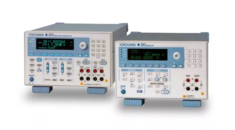
Key Specifications
MAXIMUM POWER
55WCURRENT SOURCE/ MEASURE RANGE
20 µA - 3AVOLTAGE SOURCE/ MEASURE RANGE
200 mV - 110VMEASURE RESOLUTION (CURRENT/VOLTAGE)
100 pA - 10 µA/1 µV - 1 mVFeatures
Voltage/Current Generation and Measurement Range
Four-dimensional operation with source operation (current source) and sink operation (current sink) is possible at up to 110 V, 3.2 A, and 60 W.
The output and measurement resolutions are 5.5 digits.
Voltage generation/measurement range: 200 mV to 110 V Current generation/measurement range: 20 A to 3.2 A
Maximum output current:
- 3.2 A (at an output voltage of 12 V or less)
- 2 A (at an output voltage of 30 V or less)
- 1 A (at an output voltage of 60 V or less)
- 0.5 A (at an output voltage of 110 V or less)

Generation and Measurement Timing (Source Measure Cycle)
Source measure cycle (source & measure at 1 ms minimum)
As shown in the figure below, the GS610 is capable of synchronizing the generation and measurement at any operation mode. Generation is started after a source delay with respect to an internal/external trigger. Then, after the time it takes for the source level to stabilize (measure delay) the measurement is carried out over a given integration time. This function is necessary when making measurements by waiting for the load response after applying a pulse. The source measure cycle is the minimum unit for signal generation and measurement. The source/measurement operation (source measurement cycle) on the GS610 is 1 ms minimum.
Difference Measurement Using the Sweep Operation
The sweep operation can be used to make two measurements, then the difference between the two measurements can be determined. When the source value of sweep data 1 is established, the first measurement is carried out. Then, when the source value of sweep data 2 is established, the second measurement is carried out. The difference is determined by subtracting the value of the second measurement from that of the first measurement. By carrying out the two measurements within a short time, highly accurate measurements are possible with the effects of offset fluctuation cancelled. In addition, by applying a voltage with equal magnitude but opposite in polarity (source 1 = -1 × source 2), the effects of offset error caused by the thermo electromotive force at the junction can be cancelled.


Curve Tracer Function using USB Storage
When the GS610 Source Measure Unit is connected to a PC via the USB, the PC detects the GS610 internal memory as a USB storage device. A pattern file can easily be stored in the GS610 internal memory by creating the GS610 generation pattern on a general-purpose worksheet application (1) and dragging and dropping the pattern file (2). The GS610 sweeps the voltage or current levels according to the generation pattern that is written in this file, measures the load current or load voltage at the appropriate points (3), and stores the results to the GS610 internal memory (4). A measurement result file can be retrieved into the PC by dragging and dropping. There is absolutely no cumbersome programming or installation of dedicated software programs required (5) and (6).

Zero Generation Function of Voltage and Current
The zero generation function of the GS610 enables the generation of the voltage/current zero value as well as the switching of the output condition between high and low impedance. In the zero generation condition, the voltage application or current supply to the load can be stopped with the output relay turned ON. This function avoids the problems of chattering and contact life of the output relay and reduces the ON/OFF operation time of the output.


Model
| Model | Channels | Current Source/Measure Range | Voltage Source/Measure Range | Measurement Resolution (Current / Voltage) | Power |
|---|---|---|---|---|---|
| GS610 | 1 | 20 µA - 3A | 200 mV - 110V | 100 pA -10 µA/ 1 µV-1 mV | 55W |
 SLIDE TO VIEW MORE
Series models


